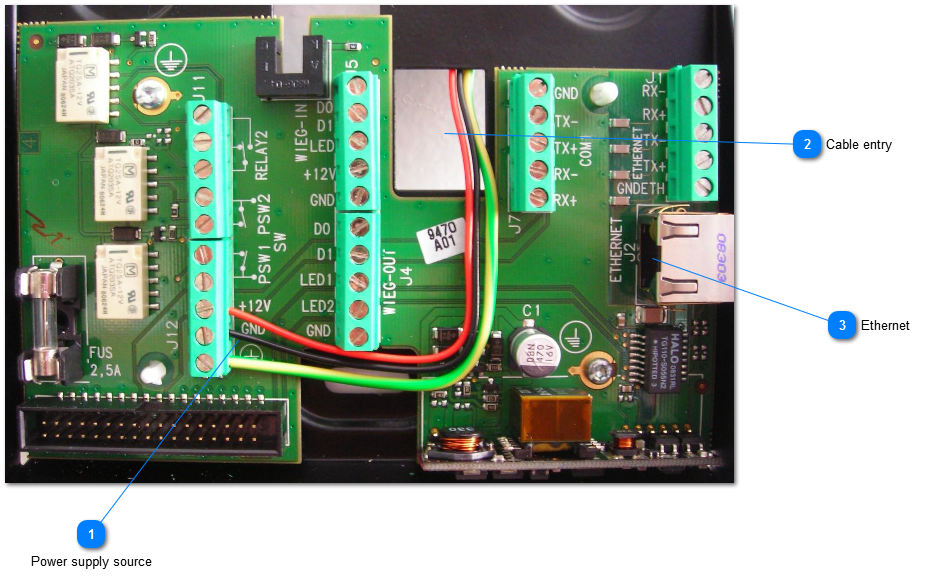
In order to connect the power and network cables, follow the steps below:
Step 1: Disconnect the ribbon cable between the motherboard and the terminal block board so that the assembly shown above can be detached from the rest of the terminal.
Step 2: Pass the connecting cables through the cable entry.
Step 3: Connect cables to terminal blocks with adequate torque conformed to screw dimensions (see the detailed instructions in MA500 Series Installation Guide). Be sure during manipulation that the power supply from the electrical source is off.
Power may come from a 12Volt Wiegand power supply, conforming to the Security Industry Association's Wiegand standard March 1995, able to deliver 9 Watts.
In standard operating activity, typical power consumption is 4.5 Watts.
In extreme temperature conditions, with all options (USB Flash drive, 12V output for Wiegand in), maximum power consumption is up to 9 Watts.
These terminals make use of POE functionality; if Ethernet network is POE compatible, power supply may come from Ethernet wiring.